Preventing Cavitation in Industrial Process Control Valves

cutaway view of mulit stage valve trim Flowserve Kammer Multi-Z
Example of multi-stage valve trim
designed to eliminate cavitation
Courtesy Flowserve - Kammer
In process control valves, cavitation results from a rapid drop in pressure as liquid passes through the valve. It results in the formation of vapor spaces or bubbles within the valve cavity. When the bubbles move downstream into a larger cross-sectional area, velocity decreases and pressure increases. The higher pressure now surrounding the bubbles causes them to implode, producing shockwaves which propagate through the liquid. These shockwaves can cause metal fatigue and excessive wear on the internals of the valve. The collapsing bubbles also make a discernible sound with accompanying vibration. The cumulative effects of cavitation can cause rapid deterioration of a valve, resulting in reduced control function, frequent need for service, or premature failure.

There are ways to mitigate cavitation. Some involve changes in the process, others, incorporating a properly designed and selected valve with trim that reduces or prevents the conditions that cause cavitation. The paper below, authored by Flowserve, provides an in depth examination of the causes of cavitation, then continues with explanation of how their specialty valves are designed to overcome the conditions that promote it.

There are detailed illustrations showing the specific valve trim features that impede cavitation. Share your process control valve challenges with application experts, combining your process knowledge with their product application expertise to develop effective solutions.


Self Defense Against Industrial Control System Cyber Threats

binary code industrial control system cyber security
Protection from cyber attacks and intrusions should be
a high priority wherever industrial automation is present
Industrial control system owners, operators, and other stakeholders should be aware of their exposure to malicious intrusion and attack by individuals or organizations intent on inflicting physical damage, stealing information, or generally wreaking havoc throughout an industrial operation. The risk of intrusion, regardless of the size or type of facility, is real and deserves the focused attention everyone involved in the design and operation of industrial control systems.

The National Cybersecurity and Communications Integration Center, part of the US Department of Homeland Security, ...
serves as a central location where a diverse set of partners involved in cybersecurity and communications protection coordinate and synchronize their efforts. NCCIC's partners include other government agencies, the private sector, and international entities. Working closely with its partners, NCCIC analyzes cybersecurity and communications information, shares timely and actionable information, and coordinates response, mitigation and recovery efforts. (from www.us-cert.gov/nccic)
The Industrial Control Systems Cyber Emergency Response Team (ICS-CERT) is a division under NCCIC. It has published a set of seven basic steps toward establishing a more secure industrial control system. I have included the publication below, and it is interesting and useful reading for all involved in industrial process control.

Having a fence around an industrial site, with a guarded entry gate, no longer provides the level of security needed for any industrial operation. Read the seven steps. Take other actions to build your knowledge and understanding of the risks and vulnerabilities. Cybersecurity is now another layer of design tenets and procedures that must be added to every control system. It will be a part of your company's best practices and success, now and in the future.

There are uncountable legacy controllers and communications devices throughout industrial America. All need to be reassessed for their vulnerability in the current and upcoming security environment. When reviewing your processes and equipment, do not hesitate to contact CTI-Controltech for assistance in your evaluation of our products.


Vertical Tubeless Boiler - Small Footprint for Hot Water and Steam Production

vertical tubeless boiler
Vertical Tubeless Boiler
Courtesy Williams & Davis Boilers
Steam and hot water are utilized in quantity throughout many industrial and commercial operations. Boilers, the most common production equipment for steam, are commercially available in a number of configurations, each with its own set of attributes making it an advantageous choice for a particular application.

One type of boiler is the vertical tubeless boiler, so named for the direction of combustion gas flow and its lack of tubes that are utilized in other designs.

Production capacity in a boiler is very dependent upon heat exchange surface area. The orientation of a vertical tubeless boiler results in a design with a significantly smaller footprint than a comparable horizontal boiler. This, obviously, can be very helpful if floor space is scarce in your facility. The rugged, simple design and lack of tubes tends to make these boilers very reliable and simple to maintain. Fueled by oil, gas, or a combination of the two, provides suitability for a wide range of facility installations. The burner is top mounted and the Williams & Davis unit pictured in this article comes fully trimmed and ready to install in most cases. Feedwater treatment and condensate return considerations are generally the same as for any other boiler.

The vertical tubeless boiler can have broad application in commercial and industrial facilities requiring a reliable source of hot water or pressurized steam. Share your hot water or steam requirements with combustion and boiler experts for the most effective solutions.

General Purpose Valve for Targeted Applications

industrial butterfly valve with actuator handwheel
Industrial Butterfly Valve
Courtesy Adams Valves, Inc.
This is the Adams Valve WEK series industrial butterfly valve. It is a general purpose valve for many applications involving fresh water, seawater, sewage, hydrocarbon and wet gas.

The WEK valves feature low operating torque, compact design, low weight, and good control characteristics. The sealing system is completely integrated within the body of the valve, utilizing a laminated metal and graphite material. Available sizes range from 3" to 24".

Streamlining promotes smooth movement of the disc through its full travel range, without flutter induced by the flow moving around the disc. Sealing is accomplished when the disc rotates to the closed position and seals tightly against the seat which is incorporated into the body. Tight shut off results from the disc pushing into the seal. Valve operation can be manual, via a handwheel, or automated with a range of electric, hydraulic, or pneumatic actuators.

Share your fluid control, valve, and automation challenges with the engineers at CTI Controltech, combining your process and facility knowledge with their product and application expertise to develop the most effective solutions.

Electro-hydraulic Valve Actuators Applied at Tank Farm

electro-hydraulic valve actuator rotork skilmatic
Electro-hydraulic valve actuators
Rotork Skilmatic
Rotork is a global leader in the design and manufacture of valve and damper actuators for industrial applications. The company's Skilmatic line of electro-hydraulic actuators is designed to provide a solution for modulating control and electric failsafe operation in rotary and linear designs. The company has created an animated video illustrating how the actuators can be deployed on control valves in a tank storage application. The presentation provides good detail of the inner workings of the actuator, along with the actuator control unit display. The video is short, but very informative.

Share your valve and automation requirements and challenges with application experts. A combination of your process and facility knowledge and their product application expertise will produce effective solutions.


Manufacturer Applies Combustion and Boiler Technology to High Temperature Fluid Generator

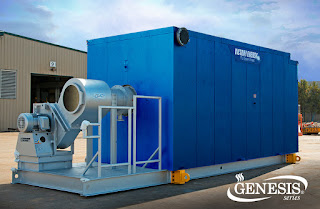
High temperature fluid generator skid mounted outdoor location
Genesis Series - High Temperature Fluid Generator
Courtesy Victory Energy
Victory Energy, an innovator in high efficiency boiler design, recently announced their new Genesis High Temperature Fluid Generator line. Victory states that the Genesis
"...heats any suitable thermal oil, glycol-water mixture or even water, with output capabilities ranging from 5 MMbtu/hr. to 200 MMbtu/hr. A complete membraned wall furnace provides gas tight construction that offers greater structural integrity while also minimizing refractory."
The company has incorporated its extensive combustion and boiler technology into the new Genesis product, which is intended for diverse applications in the petroleum, institutional, utility/power, pulp and paper, and chemical processing industries. Essentially, the unit is designed to deliver any high temperature thermal medium at the specified pressure to accommodate and enhance process operations.

Each unit is configured and engineered for the specific intended application to assure that maximum efficiency is attained. Victory's unique design provides
"...the ability to easily accommodate high differential temperatures while eliminating hot spots in the generator by controlling fluid flow evenly through the tubes."
Reach out to a combustion and boiler expert for more information on the Genesis line of high temperature fluid generators from Victory Energy.

Valtek Mark One Valve Build - Piece by Piece


Here is a video produced by Flowserve that gives an inside look at the Valtek Mark One globe control valve. The Mark One is suitable for gaseous and liquid service, and the animation illustrates the ease with which the valve can be disassembled in place for easy maintenance.

Contact a product specialist for more information and share your fluid process control challenges with them. Combining your process knowledge with their product application expertise will yield an effective solution.

LED Illuminator for Flat Panel Water Gauges

Water Level Gage Illuminator
LED Water Level Gage Illuminator
Courtesy Clark Reliance
Illuminators improve the visibility of flat panel water gages used for boiler water level monitoring. They serve as a backlight source that accentuates the display of the water-vapor line in the gage.

The DuraStar, from Clark-Reliance, can be fitted to
their flat glass panel level gages. The heatless LED illuminator is available in configurations for ordinary or hazardous classified locations. It provides high contrast visibility in all ambient lighting conditions, can be retrofitted to most existing gages, and is maintenance free.

Share your boiler trim instrumentation and control requirements and challenges with application specialists. Combine your process and facility knowledge with their application expertise to develop effective solutions.


Digital Valve Positioner Delivers Extended Functionality

digital valve positioner HART
Digital Valve Positioner
Flowserve
A valve positioner works in concert with an actuator to regulate the movement of an industrial process control valve in a predictable manner. Evolving from mechanical based designs, current state of the art positioners no longer employ mechanical means, such as cams, to establish positioner output. The latest models are software based and provide additional information and functionality to the user.
  • Loop powered device
  • Accommodates 4-20 mA input, as well as HART protocol for two way remote communications
  • Suitable for use with single or double acting actuators, linear or rotary motion
  • Certificates of approval for use in wide range of hazardous industrial environments internationally
Either of the input signal paths, analog or digital, can be utilized as the command source. When analog is selected as the input source, the 4-20 mA signal is considered the command signal. Selecting the digital source causes the level of the 4-20 mA input to be ignored and the signal sent via HART serves as the input command signal.

The software based units deliver enhanced functionality for in-field setup and calibration, as well remote monitoring and setup via HART. Multiple operating modes are accessible to the user to properly characterize valve position to desired curves, one of which can be customized. An analog feedback signal of the stem position is provided as an output.

There is more to learn. The document below goes into more depth about the features, specifications and options, with a good illustration of the user interface and screen shots taken from the SoftTools software suite that works with the digital positioner. Reach out to a valve control specialist with your requirements and challenges. The combination of your process knowledge and their product application expertise will produce effective solutions.


Type K Vane Actuator Provides Long Term Solution for Tough Power Plant Application

Rotork K-TORK vane type valve actuators on bottom ash spray valve control.
bottom ash spray valve control.
Rotork K-TORK vane type valve actuator has solved a difficult flow control application found in many coal-fired power plants – high-pressure bottom ash spray valve control.

High-pressure spray water is used to sluice bottom ash and pyrites from the boiler hopper bottoms and to carry the ash out of the plant. The valves used are typically ANSI Class 300 double-offset high-performance butterfly designs ranging in size from 3” to 12”, automated with double-acting actuators. They cycle from four to ten times per day and discharge to atmospheric pressure, creating a very high pressure drop. The flow media is re-circulated ash water that is abrasive and flows at pressures between 400 and 500 psi.

In many power plants around the world, K-TORK actuators have provided over 10 years of maintenance-free service whilst preserving the life of the valves and valve seats in this arduous duty.

Among the challenges, it is imperative that the valves close fully and with zero leakage in a high pressure drop state. If the valve disc moves even slightly from the seat, the abrasive, high-pressure water will “wire-draw” or cut the butterfly valve seat. Traditionally, rack-and-pinion or scotch-yoke actuators have been used in this application, but “slop” or hysteresis in the rotary-to-linear conversion allows for the pressure in the pipe to move the disc from the seat, often causing premature failure of the valve after a period of only three to twelve months.

The problem becomes more acute when multiple valves are leaking, lowering the available back-pressure at the header, which makes it difficult or impossible to move the ash from the boiler.

When assembled to the valve with a ‘No-Play’ coupling, the K-TORK actuator has zero lost motion, “slop” or hysteresis. The one-piece vane and drive shaft cannot be back-driven and will hold the disc of the valve firmly in place.

Additional challenges include the location of the valves on a manifold at the bottom of the boiler where space is critical and plant air can be poor quality. K-TORK provides a high torque-to-size ratio and the double-opposed lip seal design is forgiving to dirty or contaminated air.

Also, the low-friction performance of K-TORK provides a speed-controlled, smooth valve operation, eliminating the risk of water hammer created by the high pressure drop.

Finally, longer run time between shutdowns demands increased reliability from the equipment in these critical applications. In particular, as the number of plant maintenance personnel has decreased, actuators that reduce maintenance (seal replacement) time and work orders have a direct payback to the owner, especially when valve life can be significantly increased through improved actuator performance.

Share your fluid control and valve actuation challenges with a specialist, combining your process knowledge and experience with their product application expertise to develop effective solutions.

Concentric vs. Double Offset Butterfly Valve

high performance butterfly valve double offset double eccentric with actuator
High Performance Butterfly Valve
(double eccentric)
EBRO Armaturen
Butterfly valves serve a broad range of applications throughout fluid processing industries. Among their positive attributes, quarter turn operation and compact design make this valve type a primary selection for many shutoff applications.

Within the butterfly valve family, their are several basic design subdivisions that are substantial to the point of limiting or expanding the potential application of the valve. One of those subtypes is the double offset butterfly valve.

A general purpose (concentric) butterfly valve, often referred to as a resilient seated butterfly valve, has a disc connected to a rotating shaft. The rotational movement of the shaft positions the disc to fully obstruct the flow path (closed) or provide continuing degrees of open space in the fluid path cross section (open). The rotational movement of the shaft from fully open to fully closed is 90 degrees. The shaft is centered in the pipe bore and is also centered on the disc. This shaft orientation will cause the disc to contact the sealing surface throughout a considerable portion of the rotation nearing closure. This contact tends to accentuate wear on the resilient seat and limits the pressure rating for this type of valve.

A double offset butterfly valve is also known by two other common names, "double eccentric" and "high performance". The "offsets" refer to the position of the shaft relative to the pipe bore and the centerline of the disc. In this valve design, the shaft is behind the centerline of the disc and slightly to one side of the pipe bore centerline. This results in a different travel path for the disc as it moves from the open to close positions. The cam action movement of the disc limits its contact with the seat until the final few degrees of travel. The limited wiping contact of the seat tends to extend its useful life. Additionally, this type of closure movement affords the double offset butterfly valve a higher pressure rating than the concentric design.

Valve selection can be a challenging task, with numerous types and variants from which to choose. Share your industrial valve requirements and challenges with a valve specialist, combining your process knowledge and experience with their product application expertise to develop an effective solution.

Wetback vs. Dryback Firetube Boiler

firetube boiler
Victory Energy firetube boiler, Frontier series, will
be available in a dryback version
Differing boiler designs will provide their own array of positive attributes with regard to boiler efficiency, intended use, maintenance burden, and other factors. One distinguishing feature of firetube boilers is whether they are "wetback" or "dryback" design.

Not surprisingly, the difference between these two designs can be found at the "back" of the boiler, the end opposite where the fuel and air are introduced and ignited. The "wet" and "dry" designation indicates whether the firetubes, as they extend to the rear end of the boiler, discharge the hot gases into a reversing chamber surrounded by boiler water (wet) or partially isolated from it (dry).

A dryback boiler has a rear wall lined with refractory. The rear wall forms one side of the reversing chamber on a multi-pass boiler. While the refractory is certainly a point of long term maintenance, its presence as a heat sink has been noted to assist in maintaining setpoint pressure during a boiler off cycle. This tends to lengthen the off cycle of the boiler and provide some benefit. The dryback design will also have appropriately sized access doors or panels on the rear of the boiler to provide for maintenance, thus a space requirement particular to this design.

A wetback (thankfully, also called a water-back) boiler will generally have a reversing chamber constructed of steel that is contained within the confines of the boiler pressure vessel. There will be water between the reversing chamber and the boiler rear wall. Generally, the service access required at the rear of the boiler is less than for a dryback.

Victory Energy manufactures both wetback and dryback boilers in a number of configurations to meet a wide range of needs. Their extreme duty series, designated Frontier, has traditionally been a wetback boiler, but manufacturing of dryback versions is planned. The dryback product range will extend from 50HP to 2500HP and cover applications in the industrial and commercial spaces.


Rotork Wireless Valve Monitoring

Components of wireless valve monitoring system Rotork RI
Wireless valve monitoring system
Courtesy Rotork
Rotork, a global leader in valve automation, has introduced a new wireless valve position monitoring system that transmits real-time valve position indication to a central control location. The RI Wireless product line is certified Zone 1 Intrinsically Safe and intended for application in new and existing facilities in process industries and utilities.

In operation, each valve will have a Valve Monitoring Device (VMD) installed on the existing or new actuator using industry standard interfaces. The VMD gathers data from the actuator and transmits it across a network established using other routing hardware that is part of the total system. A software package provides the final connection to a receiving monitor or controller using industry standard connections.

There is more to be learned about the operation and benefits of the wireless valve monitoring system. The document included below provides description of the various devices that comprise the complete system, as well as the benefits that can be derived from its deployment. Reach out to a valve automation specialist and share your requirements and challenges. Combining your process knowledge with their product application expertise will produce effective solutions.


Predictive Emissions Monitoring Systems

Fossil fuel burning electric power plant
Predictive emissions montioring can be used for meeting
compliance requirements
Around the world, air quality standards require various levels of emissions monitoring to assure that excessive levels of harmful chemicals are not spread throughout the environment. The monitoring of emissions involves the application of sensors and processing equipment to provide information regarding the amount of specific pollutants discharged by a plant or process.

A continuous emission monitoring system (CEMS) consists of equipment necessary for determining the concentration of a gas or particulate matter, or emission rate, using analyzer measurements and subsequent data processing to provide results in units pertaining to an emission limitation or standard. This type of monitoring system is applicable where required by statute or regulation, but can also be used to provide valuable combustion or process efficiency data to plant operators.

A predictive emissions monitoring system (PEMS) employs an empirical computer model which will relate the inputs of a combustion system (air and fuel) to the emissions produced by the process. Once the model is established for a particular installation, the emissions can be predicted continuously with accuracy in the range of CEMS. There are instances where this type of system will fulfill governmental compliance requirements, in place of CEMS. PEMS can also be deployed as a complement to a hardware based CEMS. Plant conditions and an engineering evaluation will determine the best implementation of emissions monitoring equipment and systems to meet regulatory requirements and provide the level of risk management needed.

Share your emissions compliance and monitoring requirements with combustion and instrumentation experts. The combination of your process knowledge and their product application expertise will produce effective solutions.


Trunion Mount Ball Valves in Double Block and Bleed Assembly

Double block and bleed valve assembly
Valbart - Flowserve

The nature of some processes, as well as applicable industry standards, can call for a specific valve arrangement that provides isolation of a piping section with a safety factor not inherent in a standard stop valve.

Combined into a single compact unit, a double block and bleed valve consists of two trunnion mounted ball valves and a third smaller valve. While it is possible to employ other valve types in place of the ball valves, the trunnion mounted ball valve is well suited for the heavy duty applications involved in the oil and gas industry.

Each of the ball valves serve to block the process flow and the third valve serves as the bleed or drain valve for the space between the two block valves. Combining both ball valves into a single unit reduces leakage paths, weight, and installation complexity.

In addition to serving as a positive isolation valve set, a double block and bleed is also applied in meter calibration. Calibration of the meters used for custody transfer must be accomplished with a confirmed zero flow rate. Any valve leakage has the potential to impart an offset of the zero value on the meter, resulting in continuously incorrect readings. Closing off the flow with a double block and bleed valve, draining the inter-valve space with the bleed valve, then monitoring the bleed port for any continued flow can confirm zero flow in the metered line.

Share your process piping and fluid control challenges with an application specialist, combining your process knowledge with their product application expertise for the most effective solutions.


Liquid Flow Measurement - Magnetic Flow Meters

electro magnetic flow meter flow measurement
Magnetic Flow Meter Assembly
Azbil
There are many technologies available for measuring liquid flow in industrial fluid processes. Each method has its own set off attributes that will make it an advantageous selection for some applications. A familiarity with those attributes can help you make an effective selection.

Magnetic flow meters, also called electromagnetic flow meters or "magmeters", operate on a very simple principal. An electrically conductive liquid moving through a magnetic field will generate a voltage that is related to the velocity of the liquid. Magnetic flow meters have no moving parts and present little to no pressure drop to the piping system into which they are installed. It is a flow-through device and does require the cross section of the pipe to be completely filled by the subject fluid in order to produce a useful reading.

Some characteristics of magnetic flow meters.

  • Sensor assembly has no moving parts.
  • The subject fluid must be electrically conductive.
  • Measurement reflects fluid velocity and is not impacted by viscosity, density, or static pressure.
  • Other than regular calibration and operational checkout, no maintenance requirements.
  • Produces velocity reading only. Need other inputs to produce a mass flow value.
  • Bidirectional flow measurement is possible.
  • Little or no pressure drop associated with the instrument.
  • Comparatively higher in weight.
  • Accurate measurements require entire pipe cross section to be full of fluid.
There is more to know. A data sheet is included below that details the Azbil Smart Two-wire Magnetic Flowmeter. For even more information, reach out to a process measurement specialist and share your flow measurement challenges. Combining your process knowledge with their product application expertise will lead to the most effective solutions.


Electric Valve Actuator - Inner Workings

electric valve actuator with manual handle Rotork IQ3
IQ3 Electric Actuator
Rotork
Rotork's IQ3 electric actuator is one of the most advanced and full featured valve actuators available today. The IQ3 incorporates many innovative features which expand its functionality, making it an advantageous choice for many industrial applications. In just the latest generation, a number of new features have been incorporated (from Rotork website).
  • New intuitive user interface
  • Advanced dual stacked display with configurable datalogger functionality
  • Toughened glass screen plus optional environmental shield
  • Setting tool with secured Bluetooth® connection
  • High reliability, solid-state controls (multi-turn variants)
  • Reduced internal wiring and connections
  • Simplified torque sensor (multi-turn variants)
  • Simple and robust absolute position sensor with high reliability and accuracy
  • New thrust base design (multi-turn variants)
  • Separable gearbox/thrust base across the range (multi-turn variants)
  • Advanced real-time status reporting
The video below provides a display of the parts assembly of an IQ3 actuator. The mechanically inclined should find it interesting. You can get more detail on the IQ3 series of actuators for every application from a product specialist. Share your valve and actuator challenges with experts and get the best available solutions.

Power Source for Hydraulic Valves and Dampers

self contained hydraulic power unit for valve and damper actuation
Self contained hydraulic power unit
Rotork
A range of fluid processing and other flow control operations employ hydraulically actuated valves or dampers. Hydraulic actuators use a pressurized incompressible liquid as the motive force to drive the actuator mechanism. They are generally capable of operating large loads at higher speeds than electric actuators, and a smaller size than similarly capable pneumatic actuators. They are not subject to limited run times, power loss, or air line freezing.

A power unit is required to provide adequate hydraulic fluid and pressure for each application. A single unit can service more than one actuator or damper.

Rotork, a globally recognized manufacturer of valve actuators, also provides self contained hydraulic power units specifically tailored to applications involving valve and damper actuators. With fluid capacities up to 7,500 liters (2,000 gallons) and operating pressures up to 345 bar (5,000 psi), the skid mounted units are suitable for a wide range of applications. Each system is customized to accommodate the requirements of the intended application.

Share your fluid control and valve actuation challenges with product specialists, combining your process and project knowledge with their product application expertise for effective solutions.


Lined Ball Valves Provide Corrosion Protection Without Exotic Alloys

cutaway view lined ball valve for industrial fluid process control
Cutaway view of lined ball valve
Flowserve Atomac
Ball valves are a staple of fluid process control, delivering a host of design and performance attributes making them the valve of choice for many applications. When the process involves corrosive fluids, steps must be taken to accommodate the aggressive nature of the media, so that valve trim and body are not prematurely degraded by the intended use.

A good solution for valves exposed to aggressive media is an interior lining of fluoropolymer or other material resistant to the corrosive effect of the fluid. Employing a lining protects the valve metal parts from contact with the fluid, allowing the use of less expensive metals in the construction of valve body and other valve components. In extreme cases, ball valves can be delivered with fluid paths fabricated of ceramic material for superior corrosion and erosion resistance.

Flowserve Atomac is a globally recognized leader in the manufacture of lined ball valves, as well as lined strainers, sight glasses, sampling valves, and check valves. Lined ball valves are available in essentially all the configurations expected of more conventional ball valves, including diverter and control service versions.

An overview of the Atomac line is included below. Share your corrosive fluid processing challenges with a product specialist, combining your process expertise with their product application knowledge to deliver effective solutions.


Smart Boiler Level Indication Delivers Operational Benefits

LED display of boiler water level on smart level measurement and control system
Smart level control delivers operational benefits
Maintaining proper water level in a boiler is necessary for safe and efficient operation. Historically, boiler level measurement and control were accomplished with mechanical means. Today, sensor technology, electronics, and software bring improved accuracy and a host of other useful features to the water level control system.

Clark Reliance, a globally recognized leader in level indication and control, separation and filtration for steam systems, has developed a smart boiler level indication system to enhance boiler operation. The video included below provides an illustrative overview of the system, how it works and the benefits it will bring to a new or retrofit installation.

Share your combustion and steam challenges with experienced specialists, and combine your site and project knowledge with their expertise to deliver an effective solution.

Specialized Valve Trim Controls Flow and Pressure Drop


Fluid process control operations can entail fluid velocities, pressures, or other characteristics that can prove challenging on a number of levels, not the least of which is flow control. Valve manufacturers have developed a wide array of specialized designs and configurations to provide flow control while mitigating or eliminating some undesirable effects associated with restricting fluid flow.

Inherent in the restriction of flow is the possibility of creating or increasing some generally undesirable conditions in the pipe.
  • Velocity
  • Noise
  • Vibration
  • Erosion
  • Cavitation
Depending upon the process conditions, any of these elements could have a decidedly negative impact upon process performance, workplace environment, or system longevity. The video provides an example of how one manufacturer of severe service ball valves, Mogas, modifies their design to address these potentially negative aspects while providing accurate flow control. By adding elements to the outlet side of a ball valve, an entirely different operating profile is achieved. Watch the video for all the details, as it is well produced and illustrated.

Share your fluid process control challenges with experienced application specialists. Combine your process expertise with their product application knowledge to produce effective solutions.

New Introductory Video From CTi Controltech


CTi Controltech has released a new welcome video illustrating the company's capabilities. CTi’s expertise includes burner management and combustion control, as well as other areas of process control in the refining, power (including renewable such as geothermal and solar), food, specialty chemicals, mining, and semi-conductor industries. The company's personnel resources include engineers, technicians, and sales/support staff. CTi Controltech is strategically based in San Ramon, CA.

High Efficiency Hydronic Boilers

hydronic boiler high efficiency
Series 3000C Hydronic Boiler
Courtesy Williams & Davis Boilers
Hydronic boilers are widely deployed in residential, commercial, and industrial settings as part of a central heating plant or process hot water system. In recent years, replacing steam boilers with hydronic units has been one way to boost efficiency and reduce operating costs. Hydronic boilers produce hot water, whereas steam boilers deliver vapor (steam) to the distribution system.

Hydronic boilers employing condensing boiler technology can achieve efficiency rates beyond 95% in some cases. The elevated efficiency results from making use of the sensible and latent heat from the combustion fuel. Additional savings are reaped from the lower operating temperature range of the entire system. Using temperature reset related to outdoor temperature, weekend and night setback operation, and operating at greater differential between supply and return temperatures can further add to the comparative savings of a condensing hydronic boiler system.
Cutaway view of hydronic boiler
Hydronic boiler with cover removed
Courtesy Williams & Davis Boilers

There are many considerations to be taken into account when selecting a hydronic boiler and associated equipment. Proper selection and coordination of the instrumentation and equipment is a key part of achieving the desired efficiency and energy savings. It is beneficial to consult with combustion experts when planning to install new equipment. Combining your facility or process knowledge with their expertise will produce the best outcomes.


Armored Liquid Level Gauges With Specialty Indicators

armored liquid level gages guages for process measurement and control
Armored liquid level gauges provide protection from
mechanical stress and impact
Courtesy Jerguson / Clark Reliance
Sight glass liquid level gauges are a mainstay of fluid processing operations that store raw materials, intermediate, or final product in tanks and other vessels. Having a direct visual indication of fluid level at the tank enhances safety and provides the all important data point about what is happening inside the tank.

These level gauges are installed on the exterior of the tank, exposed to whatever environmental or operational hazards existing or occurring at the location. Armored level gauges are appropriately named because of their construction. They are designed to resist impact and mechanical stress, as well as a range or environmental conditions.

There are generally two versions of armored level gauges, reflex and transparent. The names refer to way in which light is handled by the gauge to reveal the liquid level. One manufacturer of armored level gauges and other level instruments, Clark-Reliance, provides a good description of the two gauge types. Their brand of armored level gauges is Jerguson, and I provide their description here of the two types (source)

Jerguson® Reflex Level Gauges are ideal for clean total level indication applications for refining, petrochemical and general use applications. The reflex prisms are molded and polished to provide a crisp black-silver bi-color indication of the fluid level. As light passes into the reflex glass, if there is fluid present, the light continues through the glass and reflects off the back of the level gauge, providing a black color for fluid level regardless of the actual color properties of the process fluid. If fluid is not present, the light is reflected off the glass back towards the user, providing a shiny silver or mirror-like appearance to indicate vapor space.

Cross section of reflex level gauge 
Jerguson® Transparent Level Gauges are selected for interface level indication, dirty service or any application that requires the use of a shield to protect the glass from corrosion. A transparent gage is also known as a “thru-vision” gauge since the gauge is constructed with two pieces of flat polished glass assembled on opposite sides of the level gauge chamber. Since the user can see straight through the gauge, it is also easy to view the fluid properties, such as color, whereas this would not be possible with a reflex gauge. The use of an illuminator is always recommended on a transparent gauge.
transparent glass liquid level gauge cross section
Cross section of transparent level gauge
Selecting an armored level gauge is an exercise in preparing for known and unknown events that might disable your ability to directly read fluid level. Armored level gauges are employed extensively in chemical, petrochemical, and other industries where reliability under challenging conditions is essential. Wherever there are mechanical hazards, an armored level gauge may ultimately prove to be cheap insurance against downtime or delay.

Share your level measurement challenges with a product application specialist. Combine their product expertise with your process knowledge to produce an effective solution. Below is a data sheet for one of several series of Jerguson armored level gauges, so you can explore more detail. Contact the product application specialists for more information about larger sizes, higher vessel operating pressures, and optional configurations that will best suit your application.

Vortex Gas Flowmeter With Built-in Pressure and Temperature Compensation

Vortex flowmeter for gas with built-in temperature and pressure compensation
Azbil MVF Series Vortex Gas Flowmeter
Industrial process control operations require measurement, lots of measurement. Whether it be temperature, level, flow, pressure, or some other attribute of the process, manufacturers have always responded to customer demand with a broad array of engineered products geared toward higher performance and lower cost.

Combining related measuring functions or capabilities into a single device can result in space and cost savings, as well as simplifying maintenance operations. Azbil NA does just that with their MVF Series of vortex flowmeters for gases.

Vortex flowmeters are based upon the recognized principle of vortices being generated downstream of a blunt obstruction at a frequency dependent upon the velocity of the fluid (von Kármán effect). The fluid velocity can be combined with temperature and pressure measurements to produce a calculated mass flow. Azbil, in their MVF Series, provides built in compensation for temperature and pressure, eliminating the need for additional instrumentation. The vortex gas flowmeter provides an output signal that is proportional to the mass flow, as well as a pulse signal. The flowmeter is suitable for use with air, nitrogen, argon, oxygen, carbon dioxide, city gas (13A), methane, propane, butane, and other inert gases or mixtures outside the explosion limit range.

See the data sheet below for more detail. You can also contact product application specialists for any assistance needed to select the right configuration for your application. Share your process measurement and control challenges with product experts. Combine your process expertise with their product application knowledge to produce the most effective solutions.


Valve Actuator Video - Rotork IQ3 Absolute Encoder and Battery

industrial valve electric actuator with handwheel
One of several variants of the IQ3 Actuator
Courtesy Rotork
Industrial valve actuators are available in an uncountable range of types, styles, power ranges, and feature sets to meet the needs of industrial processes everywhere. Some applications have a requirement for the control and decision making equipment or personnel to know the valve position at all times, including when operating power may be interrupted. This scenario calls for an absolute encoder with a battery backup.

An absolute encoder assigns a unique identifier to every possible shaft position, so any reading of the encoder value will indicate the current shaft position. These devices have historically been rather complex, but Rotork has developed a radically simplified approach that provides good operability while extending the useful life of the mechanism.

The short video below illustrates the primary features of the system. More information is available from product application specialists. Share your valve actuation challenges with them, combining your process expertise with their product knowledge for the best process control solutions.

Hydraulic Actuator Specially Designed for Most Demanding Industrial Applications

chemical processing plant exterior view from distance with stacks
Chemical Processing Plant
CTI Controltech now represents MEA, Inc, manufacturer of  hydraulic actuators and control systems.

MEA Inc has been designing and building custom hydraulic control and actuator solutions for 50 years. The company provides control systems and actuation solutions across several industrial sectors, including: in refining with FCCU Slide Valves, Coker Switch Valves, Wet Gas Compressors, MOV Gate Valves and Furnace Controls; in utilities with Boiler Fan Damper Actuators, Turbine Steam Emission Valves, Feed Water Control Valves and Turbine Bypass Valves; and in Steel Production with Edge Guide and Center Guide Systems. 

Specializing in hydraulic actuator systems, the company's integrated teams can build to any requirement and deliver a robust and reliable solution designed for decades of operation. MEA provides lifecycle support for its products, with innovative service solutions facilitating ease of use and dependability of your critical equipment. A global footprint affords the company agility and experience that is always close to customer locations.

The video included below provides an operational overview of MEA's Eagle hydraulic actuator system. Request more information from the valve actuation and control specialists at CTI Controltech. Share your process control challenges with them and combine your process knowledge with their product application expertise to develop the best solutions.


Specialized Valve Actuation Systems Safeguard Critical Flow Processes

redundant hydraulic valve actuator control unit with pumps and controls on frame
Eagle Series Redundant Hydraulic Actuator
Control Unit
Courtesy MEA
Some industrial process applications are so demanding or specialized that custom, or semi-custom, products are needed to meet requirements for safety and performance that are beyond the realm of familiar product offerings. The requirements may involve the size, capacity, or particular arrangement of a component. Also, levels of risk aversion, safety, and redundancy may be a major factor in the performance requirements of a critical control element or equipment unit.

Some industries employ processes that involve the large scale control of energy. Keeping that energy under control and directed toward process completion is key to maintaining operational, financial, and safety goals. When the energy is associated with a fluid, valves of various types are employed to properly regulate and direct its flow. The control element for a valve is the actuator, which itself is driven by a controller, and all of which must together be capable of positioning the valve trim under all possible operating conditions.

 MEA is an industry leader in the design and manufacture of valve actuation systems safeguarding critical flow processes that include...

  • FCCU (Fluid Catalytic Cracking Unit) Slide Valves
  • Coker Switch Valves
  • Boiler and Furnace Damper Drives
  • Butterfly Valves
  • Plug Valves
  • Blower and Compressor Surge Controls
  • Wet Gas Compressor Controls
  • Oil Flow Control Valves

The company's most recently developed systems effectively eliminate unplanned shut downs by providing digitally controlled redundant actuators with 100% reliability and continuous control over connected valve actuators. MEA systems are easily integrated into existing networks and provide multiple levels of security and diagnostics.

MEA provides control systems and actuation solutions across several industrial sectors, including:

  • Refining
  • Utilities
  • Steel Production

Provided below is a general overview outlining engineering and manufacturing capabilities. A brief description of the product line is included, too. Browse the document and become familiar with MEA. Share your fluid control challenges with a product application specialist. Combining your process knowledge with their product and application expertise will deliver the best solutions.


Drop-In Replacement Damper Drives for Boilers and Other Combustion Operations

Rotork brand pedestal mount pneumatic damper drive, Type K Series PM
Pedestal mount damper drive, PM Series
Courtesy Rotork
Damper drives are specialty actuators that position air and flue gas dampers on combustion based systems in industrial settings. They can be linear or rotary to meet certain application requirements. The damper positioning is a process control function that is used to increase efficiency, reduce maintenance, control harmful emissions, and lower fuel consumption.

With a very large base of legacy damper drives of the rotary type already installed throughout commercial and industrial markets, there is a need for drop-in replacements for older drives that are worn or not able to provide the level of performance accuracy needed to meet modern operating demands. Rotork, globally recognized manufacturer of valve and damper actuators, has developed a product series within their damper drive line that specifically addresses the drop-in replacement of legacy damper drives.

Rotork's PM and DM Series drives, a portion of the company's Type K Damper Drive line, provide rotary operation in the 30 to 100 degree range and are available as pedestal mount or direct mount versions. As a subset of this broad offering, the company has crafted the FasTrak Series, which are preconfigured as ready-made units to replace common, older legacy damper drives. Twelve models cover the most commonly occurring pneumatic or electric damper drive replacements. The manufacturer states that the FasTrak drives will:
  • Bolt to the floor where the old drive was mounted
  • The existing link rod and clevis will attach to the FasTraK drive lever
  • Simply verify envelope dimensions to assure that there are no external obstructions
A product catalog describing the full line of Type K drive is provided below. Share your combustion application challenges with a product specialist and work together to find the best solutions.


Specialty Transmitter Isolation Valve for Tanks and Vessels

transmitter isolation valve for process control tanks level transmitter
Transmitter Isolation Valve
Courtesy PBM Valve Solutions
Fluid process control applications frequently employ tanks and vessels as part of the processing chain or for storage and holding. Level transmitters can be installed on the tank to provide indication of liquid level. While there are numerous combinations of fittings and valves that could be used to mount and connect the transmitter to the tank, one manufacturer has designed a specialized valve intended to mate a transmitter to a tank fitting with great advantage.

The specialized transmitter isolation valve minimizes dead space to prevent media residue buildup. It can be configured to accommodate CIP and drainage without process interruption. Calibration ports and industry standard mountings allow for broad application throughout the fluid process control industries.

A cut sheet is provided below, and more information and application assistance is available from process control specialists.


Boiler Efficiency - Small Gains Can Bring Big Savings

industrial boiler room with equipment and boiler
Every boiler and steam system has a unique
set of efficiency challenges
There are numerous, actually about a half million, articles on the web about boiler efficiency. Because of the scale of even modest sized boilers, small increases in production efficiency can translate into very substantial monetary savings. Even when you have squeezed that final increment of efficiency from your boiler, a closer look will likely show there is something more you can do.
Increasing boiler and steam system efficiency is not a "one and done" proposition.
Boosting efficiency will undoubtedly involve controlling elements that were not controlled before, or at least controlling them in a more rigorous manner. This means additional instrumentation and controls that were not part of the system previously. Keeping those measurement and control elements in top working order is key to maintaining operating efficiency at stellar levels. The takeaway point here is that...
Higher efficiency operation is likely accompanied by increased system complexity.
Higher efficiency results from operating within a narrower set of conditions. Excess air, combustion temperature, flue gas composition, and more must be continuously monitored and maintained within the necessary envelope to keep the goal efficiency level throughout the varying demand levels on the system. With proper implementation, this additional complexity should not be an undue burden on the system operators. Automation and functionality built into modern measurement and control elements are capable of handling the normal operation and providing notice when conditions adversely vary from predicted or required ranges.
Increased maintenance activity is an integral part of reaping efficiency savings.
Steam systems, whether for heating a commercial building or driving an industrial process, generally involve extensive piping. The consumptive devices serviced by the system, most often where steam becomes condensate, are also part of the efficiency plan. Their productive use of the process steam contributes to overall savings. If an equipment unit, through the efforts of good maintenance and control, can perform its task with 95% of it previous consumption, that is a positive return on the effort and cost expended to boost performance.
Attaining elevated efficiency can result from added equipment, but maintaining high efficiency is a function of attitude and commitment. 
It is important that the managers, supervisors, technicians and contractors responsible for the day to day operation of the system consider efficient operation as a valuable and useful goal. Diligence, discipline, and attention to detail are solid elements of a successful maintenance program.

The US Department of Energy summarizes combustion efficiency on their website.
http://energy.gov/sites/prod/files/2014/05/f16/steam4_boiler_efficiency.pdf

Combustion Efficiency

Operating your boiler with an optimum amount of excess air will minimize heat
loss up the stack and improve combustion efficiency. Combustion efficiency
is a measure of how effectively the heat content of a fuel is transferred into
usable heat. The stack temperature and flue gas oxygen (or carbon dioxide)
concentrations are primary indicators of combustion efficiency.
Given complete mixing, a precise or stoichiometric amount of air is required
to completely react with a given quantity of fuel. In practice, combustion
conditions are never ideal, and additional or “excess” air must be supplied to
completely burn the fuel.
The correct amount of excess air is determined from analyzing flue gas oxygen
or carbon dioxide concentrations. Inadequate excess air results in unburned
combustibles (fuel, soot, smoke, and carbon monoxide), while too much results
in heat lost due to the increased flue gas flow—thus lowering the overall boiler
fuel-to-steam efficiency. The table relates stack readings to boiler performance.

Combustion Efficiency For Natural Gas


Here are some items that can impact boiler efficiency and steam system operating costs. While the list may point you toward some areas that need attention in your system, a good strategy is to consult a combustion specialist and share your concerns and goals for system operation. Their expertise will be an integral part of your good decision making.


  • Minimize losses due to leaks throughout the entire connected system.
  • Rigorously follow boiler and component manufacturer maintenance schedule recommendations.
  • Establish means to provide boiler blow-down when excess accumulation of dissolved solids occurs. Conductivity monitoring can be an effective indicator of dissolved solids.
  • Insulate all steam and condensate piping and traps. 
  • Establish steam system operation at the lowest effective pressure. Special condensate return accommodations may enhance ability to operate at lower pressure.
  • Perform timely maintenance of steam traps in accordance with best practices.
  • Use energy recovery units to heat makeup water with waste heat from flue gas.
  • Add variable speed drive controls to boiler feed pumps for lower energy consumption and finer control of feed flow.
  • Monitor flue gas O2  and temperature levels to determine combustion efficiency and optimize air-fuel ratio.
  • Monitor and control air flow and fuel flow using mass flow measuring and control devices for best accuracy.
  • On systems with multiple boilers, incorporate load sensing controls that will sequence and optimize the operation of the units in response to demand.
Certainly there is more detail involved in each item listed, plus numerous other potentially energy saving activities. By continuing to properly maintain your existing system and stay informed about new equipment and technology with promising application, you will keep your steam system operating at the top end of its efficiency range.