Pressure and Vacuum Relief Valves

schematic of processing or storage tank venting system
A pressure/vacuum relief valve is part of a complete tank
control system.
Image courtesy Groth Corporation
Storage or processing tanks are a part of almost any industrial liquid processing operation. There are many considerations for the inclusion of a tank in a liquid handling system. One facet, the subject of today's post, is how to accommodate the normal exchange of balance between liquid filled space and non-liquid filled space in a tank as it is filled or drained. Vacuum and pressure relief valves are, in many cases, the best solution for tank venting.

Keeping in mind that some tank involved operations process liquids that must remain isolated or contained from the atmosphere for any of a number of reasons. The tank may be blanketed with nitrogen or another gas. The contained liquid may produce vapor which cannot be freely vented to the atmosphere for regulatory reasons. Whatever the reason, one thing is common among all these applications. The tank must remain a closed system whenever its level is not changing.

When the liquid level in a closed tank changes, the pressure of the air or vapor in the tank will also change. Filling of the tank will increase the pressure, draining will decrease it. It is necessary to offset the change in pressure to avoid tank structural damage or processing difficulties from excessive positive or negative pressure produced by the changing liquid level. Groth Corporation manufactures pressure and vacuum relief valves for processing and storage tanks. Quoting from their installation manual for pressure/vacuum relief valves...
Pressure and/or vacuum relief valves are used on liquid storage tanks and other process vessels or systems to prevent structural damage due to excess internal pressure or vacuum. Storage tanks are pressurized when liquid is pumped in, compressing the existing vapor or when rising temperatures cause increased evaporation or expansion of existing vapor. Conversely, a vacuum condition may be created when pumping out or due to falling temperature. To prevent tank damage, vapor must be allowed into or out of the tank at specified pressure/vacuum conditions. The volume rate of venting depends upon the tank size, volatility of the tank contents, the pumping rates and the temperature.
These valves have specific requirements for installation and maintenance, but their operation is simple. A weighted pallet will move by gravity to a closed position when the liquid level is static. As liquid level changes and the pressure applied to the pallet changes, it will eventually move. It is important to note that each valve is weighted for the customer's specific application, and weight factory applied to the pallet should not be modified or otherwise changed without consulting the valve manufacturer to confirm the new operating parameters.

A pressure/vacuum relief valve is not intended to be a safety valve. It's function is related to the normal operation of the tank. A safety relief valve is an additional component with differing operational requirements. Here is now Groth describes the basic operation of the pressure and vacuum relief valves, with a little editing.
Pressure Relief: As the pressure in the storage tank increases, the vacuum pallet is held shut. When the set pressure is reached, the pressure pallet lifts and relieves tank pressure to the atmosphere (or to a header if it is a pipe away valve). 
Vacuum Relief: As a vacuum is drawn in the storage tank (for example, when fluid is being pumped out), the pressure pallet is held shut. When the vacuum setting is reached, the vacuum pallet lifts and air is drawn into the tank from the atmosphere.
Selecting and specifying a properly sized pressure/vacuum relief valve requires consideration of all aspects of tank operation. Share your project requirements with a product application specialist and leverage your own process knowledge and experience with their product application expertise to develop the best solution.

Flowmeter Basic Considerations

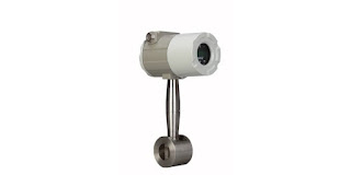
Multivariable flowmeter transmitter mass flowmeter flow temperature pressure
This multivariable vortex flowmeter provides output
of temperature, pressure and flow.
Image courtesy Azbil N.A.
Flow measurement, the quantifying of a point passage rate for gasses and liquids, is used throughout process applications in power generation, chemical manufacturing, petrochemicals, pulp and paper, water and wastewater, bio-science, semiconductor and many other manufacturing processes. There are two measurements of fluid flow in use: volumetric and weight or mass.

Flowmeters are used to measure the rate or quantity of fluid flow in an open or closed system. They are frequently found installed on piping systems, though there are also instruments capable of measuring liquid flow in open channels. The various measurement technologies have differing installation criteria, with some requiring placement of a sensing element in the flow path, others merely in contact with the flow medium, and still others with no media contact needed at all.

Flow measuring devices can be categorized in a few ways:
  • Inferential Types: Such as variable area flowmeters (rotameters), target flow meters and turbine flow meters.
  • Electrical Flow Meters: Such as electromagnetic flow meters, ultrasonic flowmeters and laser doppler anemometers.
  • Mechanical Type: Such as orifice plates, venturi tubes, flow nozzles, pitot tubes, positive displacement meters and mass flow meters.
  • Other: Such as vortex shedding flow meters, Coriolis, cross-correlation flowmeters, purge flow regulators, flow meters for solids flow measurement and flow switches.
Flow measurement instruments can be integrated into existing fluid transfer systems or installed on new lines, either inline or via insertion. Inline flowmeters mount in the piping system using downstream and upstream connections. Immersion flowmeters use a probe or sensor penetrating the piping, positioning the sensor in the flow stream.

For best results, it is important to heed manufacturer recommendations for installation. There are various flow characteristics that may have an adverse impact on measurement accuracy. Providing flow conditioning structures or maintaining minimum required straight runs on the upstream and downstream piping may be a requirement for some instruments. Each measurement technology will have installation recommendations and limitations.

For proper selection criteria, you should always know the physical state of the process media (solid, liquid, gas, steam), the condition of the media (clean, dirty, viscous, corrosive, flammable), piping size and range of flow rate. The process pressure and temperature can have an impact, as well.

Share your flow measurement challenges with a process measurement specialist and leverage your own knowledge and experience with their product application expertise to develop an effective solution.


Sanitary Tank Bottom Valve

two-way sanitary tank drain valve cutaway view
Cutaway view of specialty ball valve configured as a
tank bottom valve.
Image courtesy PBM Valve Solutions
PBM Valve Solutions manufactures a special ball valve adaptation that functions as a drain valve, or bottom valve, on sanitary process tanks. This is just one of many specialties from the company that provide the perfect solution for targeted application challenges in fluid processing.

The IGENIX® two-way valve has a formed inlet pad that facilitiates drainage and minimizes the pocket area above the ball. The full size port and several other features accommodate the needs of sanitary process operations.

More information is provided in the cutsheet included below. Share your fluid process challenges with the specialists at CTi Controltech, leveraging your own knowledge and experience with their product application expertise to develop an effective solution.


Vortex Flowmeters

multivariable vortex flowmeter with temperature and pressure compensation
This vortex flowmeter combines, volumetric flow,
temperature and pressure measurement into a single instrument.
Image courtesy Azbil, N.A.
Vortex shedding flowmeters provide consistent process fluid flow rate measurements across a wide range of applications. These flowmeters measure the volumetric flow rate of steam, gas, and low viscosity liquids, boasting both versatility and dependability when used in conjunction with process control systems.

Vortex shedding refers to the phenomenon wherein flowing gas or liquid forms vortices around a solid obstruction placed in the flow path. The measurement technology returns an indication of the process fluid velocity, which can then be used with other data to calculate volumetric or mass flow. Vortex technology is well suited for many applications involving cryogenic liquids, hydrocarbons, air, and industrial gases. Vortex flow measurement does require contact between portions of the measurement instrument and the process media, so these flowmeters are commonly fashioned from a range of corrosion resistant materials. Compatability between the instrument construction materials and process media must be considered for every application.

The process of measuring the flow involves both the flowmeter and the ability for other instrumentation to measure the vortices themselves in order to calculate velocity. Ultrasonic sensors have become popular tools for measuring vortices. Applications involving flow measurement of high viscosity fluids are not well suited for vortex technology because extremely viscous fluids do not behave in the same manner as lower viscosity fluids when their flow path is obstructed. Splitting higher viscosity fluids into concordant vertices is extremely difficult due to the internal friction present in highly viscous liquids.

Additionally, in order to split these process liquids, the piping through which the process material flows must be straight, and disturbance or vibration in the pipe may impact the measurement. A vortex flowmeter will be in a fixed installation. This stationary element, operating without electrodes, can be advantageous for flow measurement in chemical applications utilizing low viscosity fluids.

The vortex shedding flowmeter is widely used for the measurement of steam flow. The high pressure and elevated temperature of steam, along with the variation that exists in most steam systems, have little negative impact on the operation of a vortex flowmeter. Vortex shedding flowmeters are volumetrically based in terms of measurement, but their output can be combined with other fluid measurements and data to calculate mass flow. A product variant commonly available will combine the vortex flow measurement with temperature and pressure compensation, delivering three process measurements from a single installed device.

Whatever your flow measurement challenge, share it with process measurement specialists and leverage your own knowledge and experience with their product application expertise.