Showing posts with label industrial valve. Show all posts

Linear and Quarter-turn Industrial Valves

Linear and Quarter-turn Industrial Valves

Various valves are designed and used for multiple roles in process control. Linear and quarter-turn valves are two types of valves used to regulate and control fluid flow in the industry. Their design and construction reflect the intended use of the valves, with each suited to a different class of service. 

All valves work by controlling the position of an internal structure that obstructs fluid passage to some extent. In general, fluid flow at the valve classifies as unrestricted (valve fully open), stopped (valve fully closed), or throttled (valve partially open). The operational requirements of the process will determine whether only two of those conditions (fully open and fully closed) or all three are required. When choosing an appropriate valve, the fluid, the process, and the surrounding environment must be considered. It is not always a simple task. 

Linear valves distinguish themselves using straight-line motion to position the valve plug, disc, diaphragm, or other flow controlling elements. The linear valve trim's shape, size, and arrangement provide the operator with a flow range through the valve. The linear valve's positioning allows it to regulate fluid flow slower but more accurately. Linear motion valves include gate and fixed cone valves—linear valves best suit flow control.

Quarter turn valves move from fully open to closed by rotating a shaft connected to the controlling element 90 degrees. Their relatively simple operation allows for a rugged and compact design. The ability of quarter-turn valves to quickly reposition from open to closed positions is one of their distinguishing features. The torque required to operate the valves is typically low to moderate. Quarter turn valves include ball and butterfly valves. 

Depending on the situation, linear valves and quarter-turn valves are the best choices for specific process environments. The linear valve's accuracy and ability to move in a linear fashion rather than a quarter-turn come with easy maintenance and a lower likelihood of cavitation. Both valve types are widely used and are not competing for the same application. Each excels in a specific set of applications.

https://cti-ct.com
925-208-4250

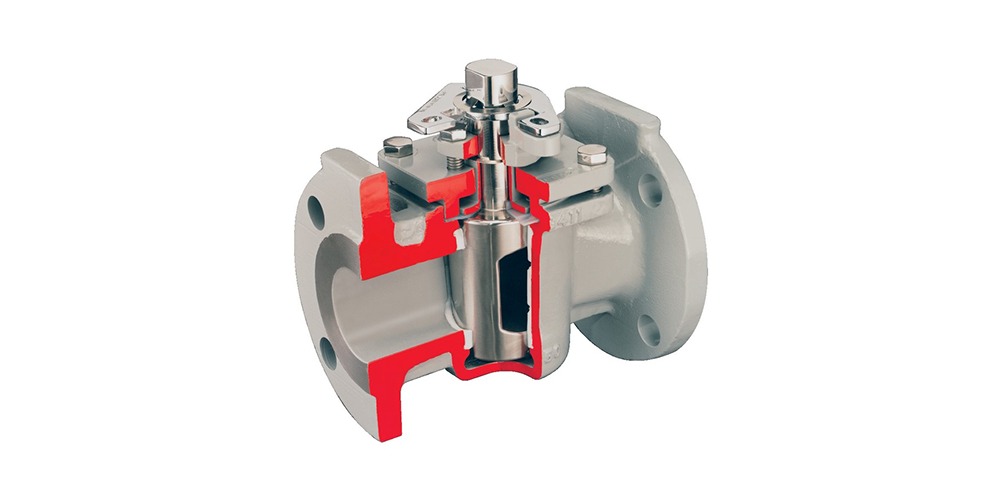
Fluid Processing - Plug Valves

plug valve cutaway view
Plug valve cutaway view
Image courtesy Flowserve - Durco
Fluid process control operations commonly employ pumps, piping, tanks and valves as the means of transporting, containing and controlling the fluid movement through a system.

Valves, of which there are many types, provide control over the flow rate, direction and routing of fluids in a processing operation. Flow can be started, stopped or modulated between zero and full rate using a properly sized and configured valve. Some valves enable media flow to be diverted to a selection of outlets, in lieu of a single inlet and outlet pair. Specialized valves regulate inlet or outlet pressure, or prevent fluid flow from going in an undesirable direction. All of these capabilities are packaged into differing valve product offerings that present a very large selection array to a process designer or engineer.

Industrial flow control valve types are generally classified according to the structure or arrangement contained within the valve body that provides obstruction to fluid flow. Some of the common types are ball, butterfly, gate, globe, and plug. Surely, there are more valve types, and this article is not intended to list them all. Some of our previous blogs have discussed selection considerations for gate, ball and butterfly valves. This article will focus on one of the oldest valve types, the plug valve.

Plug valves, like ball and butterfly valves, span from fully open to fully closed positions with a shaft rotation of 90 degrees. The “plug” in a plug valve is installed in the flow path within the valve body and rotated by means of a stem or shaft extending to the exterior of the body. Plugs are often tapered toward the bottom and are fitted to a seating surface in the valve body cavity that prevents fluid from bypassing the plug. An opening through the plug, the port, can be shaped to provide particular flow characteristics. There are numerous variants of the basic plug valve which may make it suitable for particular applications. One common variant is the lined or sleeved plug valve, with an insert or interior lining of material that creates an isolating barrier between the valve body and the media. This allows use of less expensive materials for the body construction that may be otherwise subject to corrosion by exposure to aggressive media.

Plug valves can be selected for a number of attributes.
  • 90 degree rotation from open to closed provides fast operation.
  • With proper configuration, can be well suited for frequent operation.
  • Availability of corrosion resistant liner may provide comparative cost savings because valve body can be constructed of less expensive material.
  • Design is simple and employs a low parts count.
  • Valve can be serviced in place.
  • Generally, low resistance to flow when fully open.
  • Reliable leak-tight service due to tapered plug wedging action, replaceable sleeve, and injection of lubricant in some variants.
Potential issues of concern for plug valve application include a short list of items.
  • Higher friction in the plug closure mechanism may require comparatively higher operating torque than other valve types.
  • Without a specially designed plug, generally not well suited for throttling applications.
  • Rapid shutoff delivered by plug design may not be suitable for some applications where hammering may occur.
Share your fluid control application challenges with a valve and automation specialist. Leverage your own knowledge and experience with their product application expertise to develop an effective solution.

Pneumatic Control Valve Positioners

smart valve positioner for pneumatic process control valve
Smart valve positioner
Courtesy Rotork
Valve positioners can provide process operators with a precise degree of valve position control across the valve movement range, as well as information about valve position. A relationship exists between applied pneumatic signal pressure and the position of the valve trim. The relationship between the two elements is dependent upon the valve actuator and the force of the return spring reacting to the signal pressure. In a perfect world, the spring and pneumatic forces would reach equilibrium and the valve would return to the same position in response to an applied signal pressure. There are other forces, however, which can act upon the mechanism, meaning the expected relationship between the original two elements of pressure and position may be offset. For example, the packing of the valve stem may result in friction, or the reactive force from a valve plug resulting from differential pressure across the area of the plug may be another.
While these elements may seem minor, and in some cases they are, process control is about reducing error and delivering a desired or planned output. Inclusion of a positioner in the valve assembly can ensure that the valve will be set in accordance with the controller commands.

Each positioner functions as a self-contained small scale control system. The first variable in the positioning process is the current valve position, read by a pickup device incorporated in the positioner. A signal which is sent to the positioner from the control system, indicating the desired degree of opening, is used as the setpoint. The controller section of the positioner compares the current valve position to the setpoint and generates a signal to the valve actuator as the output of the positioning process. The process controller delivers a signal to the valve, and then the positioner takes that signal and supplies air pressure required to accomplish the needed adjustment of the stem position. The job of the valve positioner is to provide compensatory force and to act as a counterbalance against any other variables which may impact valve stem position.

Magnetic sensors can be employed to determine the position of the valve stem. The magnetic sensor works by reading the position of a magnet attached to the stem of the valve. Other technologies can be employed, and all have differing ways of overcoming degrees of inaccuracy which may arise with wear, interference, and backlash. In addition to functioning as a positioner, control valve positioning devices can also function as volume boosters, meaning they can source and subsequently ventilate high air flow rates from sources other than their pneumatic input signal (setpoint). These devices can positively affect and correct positioning and velocity of the valve stem, resulting in faster performance than a valve actuator solely reliant on a transducer.

The inclusion of a positioner in a control valve assembly can provide extended performance and functionality that deliver predictable accurate valve and process operation. Share your valve automation requirements with a knowledgeable valve automation specialist and combine your process knowledge and experience with their product application expertise to develop an effective solution.

Rack and Pinion Style Pneumatic Valve Actuator

pneumatic rack and pinion valve actuator
One example of a pneumatic rack and pinion valve actuator
Courtesy Rotork
Three primary kinds of valve actuators are commonly used: pneumatic, hydraulic, and electric.
Pneumatic actuators can be further categorized as scotch yoke design, vane design, and the subject of this post - rack and pinion actuators.

Rack and pinion actuators convert linear movement of a driving mechanism to provide a rotational movement designed to open and close quarter-turn valves such as ball, butterfly, or plug valves and also for operating industrial or commercial dampers. The rotational movement of a rack and pinion actuator is accomplished via linear motion and two gears. A circular gear, known as a “pinion” engages the teeth of one or two linear gears, referred to as the “rack”. Pneumatic actuators use pistons that are attached to the rack. As air or spring power is applied the to pistons, the rack changes position. This linear movement is transferred to the rotary pinion gear (in both directions) providing bi-directional rotation to open and close the connected valve.
rack and pinion gears animation
Rack and pinion gear
Courtesy Wikipedia

The actuator pistons can be pressurized with air, gas, or oil to provide the linear the movement that drives the pinion gear. To rotate the pinion gear in the opposite direction, the air, gas, or oil must be redirected to the other side of the pistons, or use coil springs as the energy source for rotation. Rack and pinion actuators using springs are referred to as "spring-return actuators". Actuators that rely on opposite side pressurization of the rack are referred to as "direct acting".

Most actuators are designed for 100-degree travel with clockwise and counterclockwise travel adjustment for open and closed positions. World standard ISO mounting pad are commonly available to provide ease and flexibility in direct valve installation. NAMUR mounting dimensions on actuator pneumatic port connections and on actuator accessory holes and drive shaft are also common design features to make adding pilot valves and accessories more convenient.

Pneumatic rack and pinion actuators are compact and effective. They are reliable, durable and provide good service life. There are many brands of rack and pinion actuators on the market, all with subtle differences in piston seals, shaft seals, spring design and body designs. Some variants are specially designed for very specific operational environments or circumstances.

Share your process valve control and automation challenges with application experts, and combine your process experience and knowledge with their product application expertise to develop effective solutions.

High Pressure Valves for Industrial Processes and Operations

engineer working on pump and piping system oil refinery
Industrial operations present substantial
challenges to engineers and equipment
I am convinced that there is a valve out there for every conceivable application. Of course, that is not literally true, but there is an enormous array of manufacturers producing countless valve variants to meet specific requirements of the many industrial fluid processing applications.

A valve installed in a fluid process needs not only to perform its intended control function, but to stand up to the impact of several physical challenges.
cutaway view of high pressure angle valve for industrial process control
Cutaway view of high pressure angle valve
Courtesy Flowserve - Kammer
  • Temperature
  • Pressure
  • Corrosion
Any combination of these factors in the extreme can call for the use of a severe service valve. A good match between the valve ratings or capabilities and the demands imposed by the process conditions is essential for achieving safe operation and a reasonable useful valve lifespan.

Valves designed to handle very high pressure will exhibit specific attributes designed to accommodate the imposed physical stress. Body construction, assembly hardware, seats, and trim will all be noticeably heavier, stronger.

Rely on a valve specialist to contribute product expertise to the valve selection process. Combine your own process knowledge and experience with their product application expertise to develop an effective solution.


Scotch Yoke Valve Actuators

Scotch Yoke Pneumatic Valve Actuator
Courtesy Flowserve - Automax
A Scotch yoke is a mechanical linkage arrangement that converts linear motion into rotational motion. A common usage of the mechanism found in modern industry is valve actuators for quarter turn valves with high torque requirements. These applications would emerge most frequently in chemical and oil and gas industrial installations.

Quarter turn valves, such and ball, plug, or butterfly valves, only require a 90 degree rotation from their fully closed to fully open positions. In this case, the Scotch yoke is not used to produce continuous rotating motion, as it may in some engine applications. For the valve actuation case, the Scotch yoke functions much like a hand on a lever. The pneumatic variants use air pressure to drive the slider in one direction until a preset stop position is reached. Usually, a spring provides a counterforce that will drive the valve to a desired fail-safe stop position in the absence of air pressure. Other combinations of driving force and fail-safe operation are available to suit differing application needs.
Diagrammatic representation of Scotch yoke valve actuator
Illustration excerpted from Automax RG Standard Pneumatic Valve Actuator IOM 
with text added
The drive assembly consists essentially of a slider, a pin, and the yoke. The slider is moved laterally by whatever power sources are appropriate for the unit (pneumatic, hydraulic, spring, hand wheel, etc.). The pin is affixed to the slider and extends through a slot in the yoke. One end of the yoke is mounted to the valve shaft. As the slider is driven through is range of motion, the pin moves with the slider and forces movement of the yoke. This movement of the yoke translates into rotational force on the valve shaft and the repositioning of the valve trim.

Selecting and configuring the right actuator and valve for any application benefits from consultation and cooperation among the process engineers and valve automation specialists. Share your process valve and automation challenges with experienced professionals, combining your own process knowledge and experience with their product application expertise to produce an effective solution.

CTi Controltech In-House Capabilities and Solutions for Combustion, Automation, and Instrumentation

CTi Controltech has operated in northern California and Nevada for many years, satisfying customers and building their capabilities into today's top flight provider of equipment and services to industrial and commercial markets. The short piece included below is a synopsis of the company's range of products and services.

Share your combustion, emission, steam, process control, and automation challenges with experts in the field. The combination of your own process knowledge with the expertise at CTi Controltech will produce effective solutions.


Application of Limit Switches on Automated Industrial Valves

industrial valve automation actuator and limit switch
Employed in a wide range of industrial applications,
limit switches are known for ease of installation,
simple design, ruggedness, and reliability.
Courtesy Flowserve Automax
Limit switches are devices which respond to the occurrence of a process condition by changing their contact state. In the industrial control field, their applications and product variations are almost countless. Essentially, the purpose of a limit switch is to serve as a trigger, indicating that some design condition has been achieved. The device provides only an indication of the transition from one condition to another, with no additional information. For example, a limit switch triggered by the opening of a window can only deliver an indication that the window is open, not the degree to which it is open. Most often, the device will have an actuator that is positively activated only by the design condition and mechanically linked to a set of electrical contacts. It is uncommon, but not unknown, for limit switches to be electronic. Some are magnetically actuated, though most are electromechanical. This article will focus on limit switch designs and variants used in the control and actuation of industrial process valves.

Valves, devices used for controlling flow, are motion based. The movable portions of valve trim create some degree of obstruction to media flow, providing regulation of the passage of the media through the valve. It is the movement of critical valve trim elements that limit switches are used to indicate or control. The movable valve trim elements commonly connect to a shaft or other linkage extending to the exterior of the valve body. Mounting electric, hydraulic, or pneumatic actuators to the shaft or linkage provides the operator a means to drive the mechanical connection, changing the orientation or position of the valve trim and regulating the media flow. Because of its positive connection to the valve trim, the position of the shaft or linkage is analogous to the trim position and can be used to indicate what is commonly referred to as “valve position”. Limit switches are easily applied to the valve shaft or linkage in a manner that can provide information or direct functional response to certain changes in valve position.

In industrial valve terms, a limit switch is a device containing one or more magnetic or electrical switches, operated by the rotational or linear movement of the valve.

What are basic informational elements that can be relayed to the control system by limit switches? Operators of an industrial process, for reasons of efficiency, safety, or coordination with other process steps, may need answers to the following basic questions about a process control valve:

  • Is the valve open? 
  • Is the valve closed? 
  • Is the valve opening position greater than “X”? 
  • Has the valve actuator properly positioned the valve at or beyond a certain position? 
  • Has the valve actuator driven the valve mechanism beyond its normal travel limits? 
  • Is the actuator functioning or failing? 
Partial or complete answers to these and other questions, in the form of electrical signals relayed by the limit switch, can serve as confirmation that a control system command has been executed. Such a confirmation signal can be used to trigger the start of the next action in a sequence of process steps or any of countless other useful monitoring and control operations.

Applying limit switches to industrial valve applications should include consideration of:

  • Information Points – Determine what indications are necessary or useful for the effective control and monitoring of valve operation. What, as an actual or virtual operator, do you want to know about the real time operational status of a valve that is remotely located. Schedule the information points in operational terms, not electrical switch terms. 
  • Contacts – Plan and layout a schedule of logical switches that will provide the information the operator needs. You may not need a separate switch for each information point. In some cases, it may be possible to derive needed information by using logical combinations of switches utilized for other discrete functions. 
  • Environment – Accommodate the local conditions and hazards where the switch is installed with a properly rated enclosure. 
  • Signal – The switch rating for current and voltage must meet or exceed those of the signal being transmitted. 
  • Duty Cycle – The cycling frequency must be considered when specifying the type of switch employed. Every switch design has a limited cycle life. Make sure your selection matches the intended operating frequency for the process. 
  • Auxiliary Outputs – These are additional contact sets that share the actuation of the primary switch. They are used to transmit additional signals with specifications differing from the primary signal. 
  • Other Actuator Accessories – Limit switches are often integrated into an accessory unit with other actuator accessories, most of which are related to valve position. A visual local indication of valve position is a common example. 
Switches and indicators of valve position can usually be provided as part of a complete valve actuation package, provided by the valve manufacturer or a third party. It is recommended that spare contacts be put in place for future use, as incorporating additional contacts as part of the original actuation package incurs comparatively little additional cost.

Employing a properly configured valve automation package, with limit switches delivering valve status or position information to your control system, can yield operational and safety benefits for the life of the unit. Good advice is to consult with a valve automation specialist for effective recommendations on configuring your valve automation accessories to maximize the level of information and control.
Preventing Cavitation in Industrial Process Control Valves

cutaway view of mulit stage valve trim Flowserve Kammer Multi-Z
Example of multi-stage valve trim
designed to eliminate cavitation
Courtesy Flowserve - Kammer
In process control valves, cavitation results from a rapid drop in pressure as liquid passes through the valve. It results in the formation of vapor spaces or bubbles within the valve cavity. When the bubbles move downstream into a larger cross-sectional area, velocity decreases and pressure increases. The higher pressure now surrounding the bubbles causes them to implode, producing shockwaves which propagate through the liquid. These shockwaves can cause metal fatigue and excessive wear on the internals of the valve. The collapsing bubbles also make a discernible sound with accompanying vibration. The cumulative effects of cavitation can cause rapid deterioration of a valve, resulting in reduced control function, frequent need for service, or premature failure.

There are ways to mitigate cavitation. Some involve changes in the process, others, incorporating a properly designed and selected valve with trim that reduces or prevents the conditions that cause cavitation. The paper below, authored by Flowserve, provides an in depth examination of the causes of cavitation, then continues with explanation of how their specialty valves are designed to overcome the conditions that promote it.

There are detailed illustrations showing the specific valve trim features that impede cavitation. Share your process control valve challenges with application experts, combining your process knowledge with their product application expertise to develop effective solutions.


General Purpose Valve for Targeted Applications

industrial butterfly valve with actuator handwheel
Industrial Butterfly Valve
Courtesy Adams Valves, Inc.
This is the Adams Valve WEK series industrial butterfly valve. It is a general purpose valve for many applications involving fresh water, seawater, sewage, hydrocarbon and wet gas.

The WEK valves feature low operating torque, compact design, low weight, and good control characteristics. The sealing system is completely integrated within the body of the valve, utilizing a laminated metal and graphite material. Available sizes range from 3" to 24".

Streamlining promotes smooth movement of the disc through its full travel range, without flutter induced by the flow moving around the disc. Sealing is accomplished when the disc rotates to the closed position and seals tightly against the seat which is incorporated into the body. Tight shut off results from the disc pushing into the seal. Valve operation can be manual, via a handwheel, or automated with a range of electric, hydraulic, or pneumatic actuators.

Share your fluid control, valve, and automation challenges with the engineers at CTI Controltech, combining your process and facility knowledge with their product and application expertise to develop the most effective solutions.

Valtek Mark One Valve Build - Piece by Piece


Here is a video produced by Flowserve that gives an inside look at the Valtek Mark One globe control valve. The Mark One is suitable for gaseous and liquid service, and the animation illustrates the ease with which the valve can be disassembled in place for easy maintenance.

Contact a product specialist for more information and share your fluid process control challenges with them. Combining your process knowledge with their product application expertise will yield an effective solution.

Concentric vs. Double Offset Butterfly Valve

high performance butterfly valve double offset double eccentric with actuator
High Performance Butterfly Valve
(double eccentric)
EBRO Armaturen
Butterfly valves serve a broad range of applications throughout fluid processing industries. Among their positive attributes, quarter turn operation and compact design make this valve type a primary selection for many shutoff applications.

Within the butterfly valve family, their are several basic design subdivisions that are substantial to the point of limiting or expanding the potential application of the valve. One of those subtypes is the double offset butterfly valve.

A general purpose (concentric) butterfly valve, often referred to as a resilient seated butterfly valve, has a disc connected to a rotating shaft. The rotational movement of the shaft positions the disc to fully obstruct the flow path (closed) or provide continuing degrees of open space in the fluid path cross section (open). The rotational movement of the shaft from fully open to fully closed is 90 degrees. The shaft is centered in the pipe bore and is also centered on the disc. This shaft orientation will cause the disc to contact the sealing surface throughout a considerable portion of the rotation nearing closure. This contact tends to accentuate wear on the resilient seat and limits the pressure rating for this type of valve.

A double offset butterfly valve is also known by two other common names, "double eccentric" and "high performance". The "offsets" refer to the position of the shaft relative to the pipe bore and the centerline of the disc. In this valve design, the shaft is behind the centerline of the disc and slightly to one side of the pipe bore centerline. This results in a different travel path for the disc as it moves from the open to close positions. The cam action movement of the disc limits its contact with the seat until the final few degrees of travel. The limited wiping contact of the seat tends to extend its useful life. Additionally, this type of closure movement affords the double offset butterfly valve a higher pressure rating than the concentric design.

Valve selection can be a challenging task, with numerous types and variants from which to choose. Share your industrial valve requirements and challenges with a valve specialist, combining your process knowledge and experience with their product application expertise to develop an effective solution.

Ball Valves for Cryogenic Applications - Video

liquid oxygen O2 storage and distribution plant
Liquid Oxygen Storage Unit at Industrial Plant
The industrial process control field often involves the production, storage, or in-process use of cryogenic fluids. The flow control of these ultra low temperature fluids calls for valves with a particular set of design features to accommodate the pressure and temperature profile of cryogenic fluids.

Where do cryogenic temperatures start?


Wikipedia, in a description of "cryogenics" that references the field of physics, states that "It is not well-defined at what point on the temperature scale refrigeration ends and cryogenics begins, but scientists assume it starts at or below −150 °C (123 K; −238 °F)." Oxygen, hydrogen, helium, methane, nitrogen, fluorine, and LNG are all considered cryogenic liquids, having boiling points below -150°C at atmospheric pressure. Other fluids, though not considered cryogenic by the definition above, can be solid candidates for the application of cryogenic valves for reasons related to valve performance and durability in low temperature applications.

What valve design features apply to cryogenic service?


Most cryogenic service valves share a basic common set of design features that will provide basic service performance with cryogenic fluids. One manufacturer, PBM Valve Solutions, includes the following special features in their line of ball valves for cryogenic service.

  • Cleaned for oxygen service, or other high purity application.
  • Special seat and graphite seal material.
  • Special stem packing accommodates broad temperature and pressure ranges found in cryogenic applications.
  • Fire safe version available.
  • Temperature range 400°F/205°C to -320°F/-200°C with ANSI 300# Class rating.
  • Available with extended ends to eliminate requirement to disassemble valve for installation.
  • Vented balls, used to relieve pressure in the valve body, are keyed to the stem for precise assembly.
  • Extended bonnet.
  • Range of available handles or actuators for manual or automatic operation.
  • Stem can be installed 45° to 90° from horizontal plane.
The video below provides further illustration of the special design features of industrial process control valves applied for cryogenic fluids. More product details and help solving any industrial process control challenge, are available from CTI Controltech.


Industrial Valves - When Butterfly Valve Is The Best Choice

Industrial butterfly valve cutaway
Butterfly Valve
Courtesy Durco - Flowserve
Industrial process control valves are available in uncountable combinations of materials, types, and configurations. An initial step of the selection procedure for a valve application should be choosing the valve type, thus narrowing the selection field to a more manageable level. Valve "types" can generally be classified by the closing mechanism of the valve.

A butterfly valve has a disc that is positioned in the fluid flow path. It rotates around a central axis, the stem, through a 90 degree arc from a position parallel to the flow direction (open) to perpendicular (closed). A variety of materials are used in the valve body construction, and it is common to line the valve with another material to provide special properties accommodating particular process media.

What attributes might make a butterfly valve a beneficial selection over another valve type?

Manually operated industrial butterfly valve
Manually Operated Butterfly Valve
Courtesy Ebro Armaturen

  • The closure arrangement allows for a comparatively small size and weight. This can reduce the cost, space, and support requirements for the valve assembly.
  • Generally low torque requirements for valve operation allow for manual operation, or automation with an array of electric, pneumatic, or hydraulic actuators.
  • Low pressure drop associated with the closure mechanism. The disc in the flow path is generally thin. In the fully open position, the disc presents its narrow edge to the direction of flow.
  • Quarter turn operation allows for fast valve operation.
  • Some throttling capability is provided at partially open positions.
  • Small parts count, low maintenance requirements.

What may be some reasons to consider other valve types?


  • Butterfly valve throttling capability is generally limited to low pressure drop applications
  • Cavitation can be a concern.
  • Some sources mention the possibility of choked flow as a concern under certain conditions.

Butterfly valves, like other valve types, have applications where they outperform. Careful consideration and consultation with a valveexpert is a first step toward making a good selection. Combine your process know-how with the product application expertise of a professional sales engineer to produce the best solutions to your process control challenges.

Industrial Process Control Valve Quality Detail

Industrial process control valve
Wafer Style Resilient Seated Butterfly Valve
Courtesy EBRO Armaturen
Industrial process control operations have a lot riding on every component integral to the process. The operator's challenge is to get every individual element to work as planned, every time. Most process engineers would likely agree with the premise that high quality components tend to deliver higher reliability and consistent performance. Employing properly specified, high quality, componentry throughout a process installation is a generally accepted methodology for achieving the goal of consistent process output and quality.

Any process that involves fluid is bound to have valves as primary control elements. Proper selection from among the many different types used for process control, as well as the many manufacturers, can be a challenge in its own right.
How do you determine the quality level of a valve?
In industrial valves, like many products, it's in construction details that quality resides. One manufacturer, EBRO Armaturen, gives us a detailed look inside and throughout their soft seal butterfly valve. The video is included below, and it is short and to the point.

Attention to detail is what makes your operation work at its best performance level. That same level of attention also contributes to the design and manufacture of a great product. Invest two minutes to watch the video. The construction details are educational, probably things you did not know. You can get more information, or discuss your process control challenges, through contact with an application specialist.

Specialty Ball Valve - Self Cleaning Flushable

Industrial ball valve
Self-Cleaning Flushable Ball Valve
Courtesy PBM Valve Solutions
For some industrial fluid process operations, one of the shortcomings of ball valves can be their propensity to trap small amounts of process fluid when they are operated. This is troublesome on two fronts. Firstly, a process that changes media between operations can be subject to contamination from the trapped fluid. Secondly, the fluid trap is detrimental to any attempt to sanitize the process line. A variant of the common ball valve, a self-cleaning flushable version, eliminates costly downtime required to disassemble, clean and reassemble traditional valves. Self-cleaning flushable ball valves, from PBM Valve Solutions, can be used in a variety of processes including food, beverage, paints, resins, chemicals, consumer products, pharmaceuticals, and cosmetics.

In the video below, you can see how the special features of this innovative valve design work. Contact a product specialist to explore how you can bring the advantages of this innovative valve to your process.


Improved Local Display On Rotork Valve Actuators

Industrial Valve Actuator
IQM Modulating Valve Actuator
Courtesy Rotork
Rotork IQ3 Electric Valve Actuators, a product line handled by CTI Controltech, offer some innovative improvements that provide industrial process operators higher levels of reliability, accessibility, and security than previously available. Among the strong features of this product:

  • Advanced Display (detailed in the video below)
  • Asset Management
  • Bluetooth Communications Interface
  • Compact Double-Sealed Enclosure
  • Absolute Encoder (on some variants)
  • Intelligent Battery Management
  • Local Interface
  • Secure Local Controls
  • Watertight, Dust Tight, Explosion Proof
There is plenty of detail available about all the features of the solidly built IQ3 line of actuators for industrial process valve control. Watch the video and contact a product specialist to get more detail or assess your specific application needs.


Why Do We Debate Air vs. Electric Powered Valve Actuators?

Rotork Industrial Valve
Industrial Process Control Valve
Courtesy Rotork
Which is better, air or electric? We're talking about valve actuators here. Just for perspective on how original this article might turn out to be, I commanded my friendly Google search engine to look for "air vs. electric actuators". Google always finds something, no matter what you ask, giving the humble user an impression that the big "G" has all the answers....and they truly may. Don't misunderstand me. I am a big Google fan. Someday I might even pay for something that they provide me. Anyway, I was humbled by the avalanche of search returns on my the subject, 17,200,000 articles. That's a large number, even for a Google search. Many of the articles related to industrial machinery automation, not valves. Changing my search to "electric vs pneumatic valve actuator" shaved the returns down to 236K, a more manageable volume.
Dutifully reading the highest ranked articles and following threads in forums, I started to wonder why, like figurative gladiators, we pit these two valve actuator motive power sources against one another. There is not a single winner in this case. One is not universally better, more advantageous, than the other. Both methodologies have instances where they can be used to best advantage. A good recommendation is to not be too influenced by the past, by what your own industrial process control experience may have been. The manufacturers of these products are continuously modifying designs and releasing products with newer technologies and better performance that may eliminate some shortcomings of the past.

Your best course of action is to consider the following:

  • What is the expected useful life of the process? Short term, long term, permanent?
  • Will existing air supply and piping system accommodate the anticipated additional pneumatic valve load, if that type actuator seems otherwise advantageous?
  • Are there sufficient maintenance and technical resources in place to keep either system in top operating condition and successfully deal with operational and repair issues that will arise? Does the current maintenance staff have sufficient knowledge and training to perform needed tasks?
  • Are there rated hazardous zones where valves will be located?
  • What needs to happen to valve position if motive power (air pressure or electricity) fails?
  • What valve positioning requirements are associated with proper control of the process?
  • What interfaces with any existing control systems, if any, need to be accomplished?
Carefully consider these points, add several of you own. Consult with knowledgeable sales engineers that specialize in valve automation. Combine experience and knowledge from a number of sources and a good solution will materialize. 


Severe Service Ball Valves Meet Toughest Application Challenges

Industrial ball valve for severe service - section view
Severe Service Ball Valve Section View
Courtesy Mogas Industries
Industrial process control, as a field of endeavor, can expose an engineer to instances where their design input can have very significant impact on the financial prospects of their employer, even the safety and well being of the public residing near company facilities. "Getting things right the first time" is much more than a motivating slogan on a poster tacked to the wall in the corridor outside the engineering department. It is what our society demands of engineers. Fortunately, there are engineers that embrace the role of making sure things go as planned. They work as process engineers and also as designers of the componentry and equipment used to implement complex and potentially dangerous processes.

I have written about the positive and potentially not so positive attributes of ball valves for industrial process control applications. In that recent blog article, I mentioned that ...

"There may be particular ball valve variants that overcome potential shortcomings listed in this article".

Ball valves designed for severe service are an example of a manufacturer specifically designing ball valves to not only overcome some potential shortcomings of the valve type, but to extend the performance ratings into areas that accommodate some of the most demanding applications in the process control field.

What constitutes severe service?


  • Extreme temperatures
  • High pressures
  • Abrasive particulates
  • Acidic products
  • Heavy solids build up
  • Critical plant safety
  • Large pressure differentials
  • Velocity control
  • Noise control


Extended or enhanced features of severe service ball valves include:


  • Floating or trunnion mounted ball design with straight through bore path that protects the sealing surfaces.
  • Wide seat sealing surface with matched ball and seat sets that provide total sealing contact for reliable isolation. The greater sealing contact area withstands minor scratches and abrasions.
  • Independent replaceable seats to minimize repair and maintenance costs.
  • Pressure energized sealing, with seat springs that maintain a constant sealing contact between the ball and seats. Metal seats wipe the ball sealing surface clean during every operation.
  • Blowout proof one piece oversized stem design meets stringent industrial safety standards and withstands maximum working pressures and extreme service torques.
  • Dual-guided stem design employs pressure energized inner stem seals as a thrust bearing and lower stem guide. The valve stem bushing serves as the upper stem guide to eliminate lateral movement of the stem and prevent media migration and fugitive emissions.
  • Greater body wall thickness, with forged body and end connections for longest service life.
  • A heavy duty operator mounting flange, to provide structural support for the valve operator, is machined after attachment to assure precise stem alignment.
Application specific features, such as seat designs, live loaded packing, body gaskets, coatings, liners, purge ports, end connections, and special materials are also available to customize these severe service valves to meet extreme application requirements. The presentation below provides schematic and illustrated examples where severe service valves are applied and provides additional detail about the special features incorporated in the design of severe service ball valves. For all your control or isolation valve projects, whether in the conceptual, planning or implementation stage, consult a valve specialist. Merge your grasp of the process and its requirements with the product knowledge and application experience of a specialist and produce a solidly positive project outcome. 


Rotork Skilmatic Valve Actuators Enhance Performance and Safety


Valve Actuator
Electro-Hydraulic Valve Actuator
Courtesy Rotork
Incorporating levels of performance and safety into industrial fluid handling systems presents ever increasing challenges to those designing, owning, and operating those systems. Rotork Fluid Systems developed the Skilmatic line of valve actuators to provide the positioning performance, operational safety, and data connectivity needed for best-in-class implementation of industrial process control valves.

The Skilmatic range of self-contained electro-hydraulic actuators combine the precision of hydraulic control, the simplicity of electrical operation, and the reliability of mechanical fail-safe action into a single integrated product. In addition to general purpose, flameproof, and modulating versions of the actuators, Rotork offers intelligent versions of the product that deliver improved control and monitoring functions:

  • Datalogger recording of events, trends, alarms.
  • Bluetooth connectivity for data download and upload between actuator and Rotork’s InSight2 software.
  • Semi-automatic position limit calibration.
  • Partial stroke operation.
  • Improved position control for modulating operations.
  • Valve flow characterization for modulating control with various valve attributes, such as equal %, linear, and more.
  • Manual override detection.
  • Alarm output relays with selectable function.
  • Internal temperature sensor.

The actuators are available in a myriad of configurations to suit every application. A wide range of standard arrangements are offered, along with custom versions configurable to provide a specific solution demanded for a special application. A deeper profile and description of the product line, principals of operation, and operational benefits is available from a product specialist, who can also assist with selecting and configuring the right unit for your project or application.