Showing posts with label cavitation. Show all posts

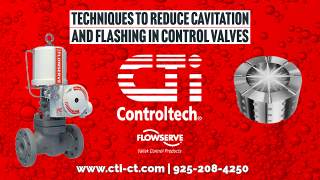
Techniques to Reduce Flashing and Cavitation in Control Valves

Techniques to Reduce Flashing and Cavitation in Control Valves

Industrial control valves are pivotal in managing fluid flow in numerous applications across various industries, including oil and gas, chemical, and power generation. A common challenge in the operation of these valves is the phenomena of flashing and cavitation, which can severely damage valve components, reduce operational efficiency, and increase maintenance costs. Manufacturers have developed several port modification techniques to mitigate these issues, enhancing the longevity and reliability of control valves. One notable solution in this area is Flowserve Valtek's CavControl technology.

Flashing occurs when the pressure of a liquid drops below its vapor pressure, causing it to vaporize as it flows through the valve, leading to erosion and wear on valve components. Conversely, cavitation happens when vapor bubbles formed from flashing collapse downstream of the valve seat in a liquid phase, causing shock waves that can damage valve parts and connected piping systems. To address these challenges, engineers have devised various port modification techniques focused on controlling the flow within the valve to manage pressure drops more effectively and reduce the likelihood of flashing and cavitation.

One such technique involves the use of multi-stage trim designs. These designs distribute the pressure drop across several more miniature stages or steps within the valve, thereby preventing the pressure at any point from falling below the liquid's vapor pressure. This staged pressure reduction minimizes the energy available for vapor formation as the fluid progresses through the valve, effectively mitigating flashing and reducing the potential for cavitation.

Another port modification approach is incorporating specially designed flow paths that smooth fluid transition from high to low pressure. By carefully shaping these paths, engineers can ensure a more gradual pressure decrease, which helps maintain the liquid state of the fluid and reduces vapor bubble formation. This method not only combats cavitation but also optimizes the flow profile within the valve, enhancing performance and efficiency.

Flowserve Valtek's CavControl technology exemplifies applying advanced port modification techniques to combat cavitation. Cavcontrol utilizes a unique trim design that manages the pressure drop across the valve in a controlled manner, effectively mitigating the conditions that lead to cavitation. The technology incorporates a series of specially engineered notches or grooves in the valve's trim that create a series of pressure-reducing stages. As the fluid passes through these stages, the pressure decreases incrementally, preventing any sudden drop below the vapor pressure and thus avoiding the formation of vapor bubbles.

Furthermore, CavControl's design also focuses on energy dissipation. Controlling the flow path and dissipating the fluid's kinetic energy throughout the valve reduces the fluid's velocity and the impact of any vapor bubbles that may form, minimizing the potential for damage. This approach extends the valve's life and ensures smoother operation and improved control accuracy.

The challenge of flashing and cavitation in industrial control valves requires sophisticated engineering solutions. Port modification techniques, including multi-stage trim designs and controlled flow paths, effectively mitigate these issues. Flowserve Valtek's CavControl technology stands out in this field, demonstrating how advanced design and engineering can enhance the performance and reliability of control valves, ensuring their safe and efficient operation in industrial processes.

CTi Controltech
https://cti-ct.com
925-208-4250

Preventing Cavitation in Industrial Process Control Valves

cutaway view of mulit stage valve trim Flowserve Kammer Multi-Z
Example of multi-stage valve trim
designed to eliminate cavitation
Courtesy Flowserve - Kammer
In process control valves, cavitation results from a rapid drop in pressure as liquid passes through the valve. It results in the formation of vapor spaces or bubbles within the valve cavity. When the bubbles move downstream into a larger cross-sectional area, velocity decreases and pressure increases. The higher pressure now surrounding the bubbles causes them to implode, producing shockwaves which propagate through the liquid. These shockwaves can cause metal fatigue and excessive wear on the internals of the valve. The collapsing bubbles also make a discernible sound with accompanying vibration. The cumulative effects of cavitation can cause rapid deterioration of a valve, resulting in reduced control function, frequent need for service, or premature failure.

There are ways to mitigate cavitation. Some involve changes in the process, others, incorporating a properly designed and selected valve with trim that reduces or prevents the conditions that cause cavitation. The paper below, authored by Flowserve, provides an in depth examination of the causes of cavitation, then continues with explanation of how their specialty valves are designed to overcome the conditions that promote it.

There are detailed illustrations showing the specific valve trim features that impede cavitation. Share your process control valve challenges with application experts, combining your process knowledge with their product application expertise to develop effective solutions.


Control Valve Cavitation - A Demonstration and Some Considerations

Cavitation in process fluid exhibits as bubbles
Cavitation can be damaging to process components.
Consider a generic industrial fluid process control operation. There are pumps, valves, and other components installed in the process lines that, due to their interior shape or their function, cause changes in the fluid motion. Let's look specifically at control valves and how their throttling operation can create conditions able to greatly impact the valve itself, as well as the overall process.

Fluid traversing a control valve can undergo an increase in velocity when passing the constriction presented by the valve trim. Exiting the trim, fluid then enters the widening area of the valve body immediately downstream with a decrease in velocity. This change in velocity corresponds to a change in the kinetic energy of the fluid molecules. In order that energy be conserved in a moving fluid stream, any increase in kinetic energy due to increased velocity will be accompanied by a complementary decrease in potential energy, usually in the form of fluid pressure. This means the fluid pressure will fall at the point of maximum constriction in the valve (the vena contracta, at the point where the trim throttles the flow) and rise again (or recover) downstream of the trim.
This is where cavitation begins.
If the fluid being throttled is a liquid, and the pressure at the vena contracta is less than the vapor pressure of the liquid at the flowing temperature, portions of the liquid will spontaneously vaporize. This is the phenomenon of flashing. If, subsequently, the pressure of the fluid recovers to a level greater than the vapor pressure of the liquid, any flashed vapor will rapidly condense, returning to liquid. This collapse of entrained vapor is called cavitation.

Flashing, the generation of vapor bubbles within the liquid, will precede and set the stage for cavitation. When the flashed vapor bubbles condense to liquid they often do so asymmetrically, with one side of the bubble collapsing before the rest of the bubble. This has the effect of translating the kinetic energy of the bubble’s collapse into a high-speed “jet” of liquid in the direction of the asymmetrical collapse. These liquid “microjets” have been experimentally measured at speeds up to 100 meters per second (over 320 feet per second). What is more, the pressure applied to the surface of control valve components in the path of these microjets can be intense. An individual microjet can impact the valve interior surfaces in a very focused manner, delivering a theoretical pressure pulse of up to 1500 newtons per square millimeter (1.5 giga-pascals, or about 220000 PSI) in water. In an operating fluid system, this process can be continuous, and is known to be a significant cause of erosive wear on metallic surfaces in process piping, valves, pumps and instruments. As the rapid change in pressure takes place, the bubbles (voids in the liquid) collapse (implode), and the surrounding metal surfaces are repeatedly stressed by these implosions and their subsequent shock waves.

Consequences for control valves, as well as for the entire control process, vary and are often destructive. They may include:
  • Loud noise
  • Strong vibrations in the affected sections of the fluid system
  • Choked flow caused by vapor formation
  • Change of fluid properties
  • Erosion of valve components
  • Premature destruction or failure of the control valve 
  • Plant shutdown
The video provides a visual demonstration, through clear piping, of what happens inside the piping system when a valve is operated in a manner that causes substantial cavitation.

The solution lies in minimizing the potential for cavitation to occur through proper valve selection and sizing, along with coordinating operating characteristics of pressure drop inducing components with the total system performance. One valve manufacturer's recommendations are summed up in four basic approaches.
  • Avoidance of cavitation through proper valve selection. Use a valve with a rated liquid pressure recovery factor greater than that required for the application. Some applications may be suitable for the use of an orifice plate downstream of the valve.
  • Cavitation Tolerant Components capable of withstanding limited amounts of cavitation without excessive wear. Increased flow noise is likely to accompany this route.
  • Prevention of cavitation through the use of valve trim design that reduces pressure in several steps, avoiding excessive flashing. These valves can be expensive, but their effectiveness makes them an alternative worth considering.
  • Containment of the harmful effects of limited to moderate cavitation through trim designs that eliminate contact of the fluid with metal surfaces which are more susceptible to damage.
Share your requirements and application challenges with a valve specialist and gain insight through their recommendations. Combining your process knowledge with their product application expertise will yield a great solution.